Receiving AIS

How to Receive AIS on Shore and Sea

Most of which you don't need to know - until it doesn't work !

Preface
I've tried to keep as much of the following a simple as possible while still including some meat for those who wish to know more about what's actually going on, or are having problems. Just stop when you've read enough to do what you want - or you're fed up -  as it gradually gets more complicated.
 
Introduction
AIS (Automatic Identification System) is used by ships to report their position, speed course and other information to other ships and shore stations, by transmitting the relevant information at regular intervals, using a VHF radio link. It is used by ships to assist in collision avoidance and other safety related issues.

AIS Basics
Although primarily intended for inter-ship and ship-to-shore communications, the signals transmitted can be picked up by any suitably equipped receiving station, enabling ships' positions to be displayed on a map or chart. The reception range is limited to VHF radio range, which is typically 10 to 40 miles.

Setting up a basic station
It is not difficult to set up a simple home receiving station. You need an aerial connected to a receiver, connected to a display. Getting the whole to work is a bit like a jig-saw puzzle, each piece has to link properly to each other piece in the chain. If one doesn't, you may have to put another piece in between to link the two together that otherwise wouldn't fit.


VHF Signal
The AIS signal is transmitted at VHF (Very High Frequency), broadly speaking this is similar to the frequency TV and FM radio is transmitted. As with TV, reception is limited to "line of sight", in other words the receiving aerial must be able to "see" the transmitting aerial. In fact reception distance is likely to be sightly greater than this, because radio waves bend a little round the Earth's surface.
Like TV reception a good aerial makes a significant difference to the reception, and height really does matter (otherwise you would not put TV aerials on chimney pots).


Antenna/Aerial
    Types
A Marine VHF aerial will give reasonable reception, for about double the price of the cheapest marine aerial the Metz Manta will take some beating. It's still considerably less than the more expensive marine aerials.
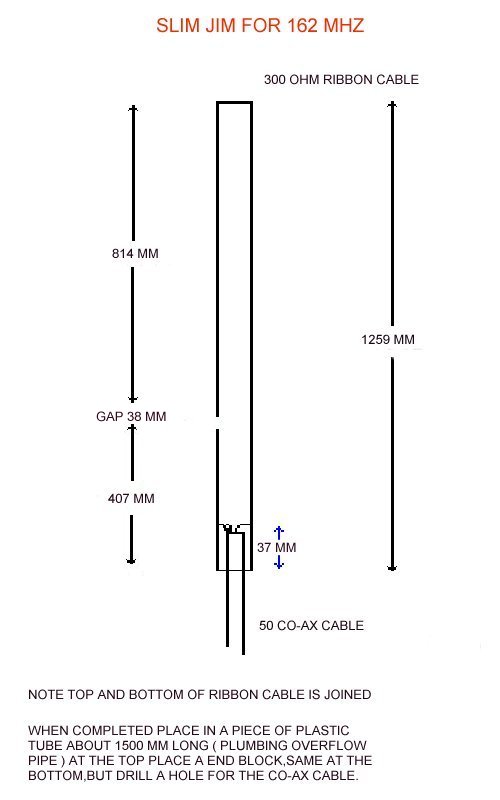
If your handy with a soldering Iron you can make a ribbon cable "Slim-Jim" for a few pence.  

    Siting
As already mentioned, the higher the better

Downlead

Commercial aerials may come with a downlead already connected, or may come with just a socket at the base of the aerial. If supplied with a lead it will probably have a  PL259 plug on the end of the downlead and your receiver will probably have a BNC connector for the aerial, in which case you will need an adapter.  

  
These are available from Maplin , Martin Lynch & Sons or worldwide from  Farnell
If no downlead is supplied you will need RF coax, which should be 50 ohm. To start with RG58 is OK, RG213 is much better (particularly for longer runs) although considerably more expensive. TV or satellite coax cable is not suitable.
 

Receiver
There are two basic options

Dedicated AIS receiver

This converts the VHF radio signal into a decoded digital signal suitable for direct connection to a PC or Chart Plotter. It is a "Black Box", There are no controls of any description, just an aerial socket, output socket and power supply (unless powered direct from a computer USB connection). The most popular are possibly NASA AIS engine, Comar and SR161/162 .

Communications/Scanner Receiver

You can also use a Communications Receiver or Scanner. This outputs audio and requires an audio decoding program running on a PC.  This is really only a practical proposition if you already have a suitable receiver or wish to use the receiver for other purposes. Not all scanners or receivers are suitable as they need to be able to receive the right frequency and importantly need a wide enough bandwidth. For more information on suitable receivers and possibly modifying an existing receiver see http://www.discriminator.nl

Receiver to PC connection

The output socket from a dedicated AIS receiver will be RS232 (serial) or USB or RJ45 (network). The output from a communications/scanner it will be a Jack (audio). The receiver must be connected to the same type of socket on the PC. The appropriate lead will probably be supplied with the receiver. If the receiver has a RS232 serial output, you can use a RS232-USB adapter lead containing both software and hardware within the socket to convert the signals. It costs around £20 from Maplin. As the electrical signal in each type of lead are different, you cannot buy a simple adapter plug to change between each type of plug and socket.

As already mentioned, a communications receiver passes an audio signal to the PC, the other three types of connection all transport identical data from the receiver to the PC. Each of these three types (RS232,USB,RJ45) uses a different method to transport the data, even though the data is identical in each case. Its a bit like receiving the same letter in the post, by hand and by fax; in each case you receive the same letter but the method of transport is different. The format of this data is called NMEA (like the envelope containing the letter) . The decoded AIS signal is encapsulated within the NMEA format.

PC Programs
A PC or possibly a chart plotter, is used to display the AIS data in a visual manner, normally on a chart or a map.
There are a number of programs available, some are free, some shareware and some commercial. Because of copyright and chart format issues, simple maps/charts can be free or can be very expensive and not all charts are compatible with all programs.
To further complicate the choice, there are programs available to scan charts and stitch adjacent charts together. There are also programs which will overlay AIS data on Google maps.
Another complication is most programs and some computers do not accept serial,usb and network connections.
Because of the number of options, and after you have received and seen your first data, your preferences may change, it is quite probable your first program may not be the program you ultimately prefer. I would suggest initially using a simple free program, get used to the type of information you wish to see and how you prefer to see it displayed, before committing significant time and possibly money in software.
ShipPlotter is free to display your own data. It accepts serial and network connections. To accept USB you will need a virtual com port driver which will allow you to use the software with a receiver using USB output. This driver is supplied with the
Comar AIS-2-USB.
SeaClear is also free and is supplied with the
NASA AIS engine. It only accepts serial input.

In my view ShipPlotter is better for home use and
SeaClear more suitable for use on a boat. SeaClear is more complex to set up if you are not using serial input.

Connection Direct to the Internet
You can run an AIS receiving station without using your own PC to process and display the received data. There are a number of websites who will display your data (as well as many others) for all to see. Marine Traffic, SIITech and ShipAIS (UK only) all provide this free service. To send the data directly to the internet, the easiest way is to use a receiver with a network output such as the Comar SLR200N, which you connect straight to your internet router using a RJ45 patch lead. If your receiver has a serial output you will need a serial to network converter such as the Didi One SP, which is inserted between your receiver and your router.
 
Using on a boat
There are some additional considerations when using AIS on a boat. You will be considering using AIS to assist you in collision avoidance. For my own peace of mind be warned, AIS is only an assistance, it is not guaranteed, don't rely solely on AIS. The information transmitted by other vessels may be incorrect, it may be non-existent.
You will however be able to see most commercial vessels at a far greater distance and know their speed & course. The use of virtual buoys will increase. AIS will give you greater peace of mind, particularly in fog.

Transponders
An AIS transponder is a receiver coupled to an AIS transmitter, assuming your vessel is under 300 tons, you will be looking at a class B transponder. The details applicable to receivers also apply to transponders. A transponder makes your boat visible to commercial vessels on their AIS display. There are a couple of significant differences between Class A (used by commercial vessels) and Class B (under 300 tons). Apart from a massive price difference, the power output of Class B is much less (2 watts, class A is 12.5 watts) and the frequency of transmission is much less. In addition in the event of slot congestion, due to many vessels being in the same VHF range, Class B transmissions are suppressed.
   
Antenna Splitter
As you will already have a VHF aerial, you can use the same aerial to receive AIS but you will need an antenna splitter such as EasyAis.
You must not connect a receiver directly to a transmitter aerial (you'll overload & probably blow up the receiver). As splitters are more expensive than VHF aerials you may opt to use a separate marine VHF aerial. This will be quite adequate for use on a boat. If you are going to use a transponder you must ensure the splitter will work with a transponder (many won't) otherwise you will blow up the splitter.
Some receivers come with a built-in splitter such as the Icom MXA-5000.

Connecting AIS to existing Instrumentation
Marine instruments normally talk to one another using NMEA, even those manufacturers using proprietary protocols provide NMEA converters so their instruments can both receive and send NMEA format data. If you are receiving AIS you will want other ships displayed on a chart, which will be either a chart plotter of a PC. If using a chart plotter, it will be connected to a GPS. If you are going to use a PC it will require a GPS input (so you know here you are on the chart). In both cases A GPS will be connected using NMEA input.
In NMEA terminology, a device connected to other NMEA devices is either a "talker" a "listener" or both. NMEA  allows one talker to be connected to a maximum of 3 or 4 listeners, without using a buffer. In practice I have connected more than this without a problem. The NMEA voltage levels are also different to the voltage levels on a PC RS232 interface. Again in practice this does not seem to be a problem with modern PC's. If you put more than one talker on the same line at the same time some sentences will become garbled if both talkers talk at the same time (and there's a fair chance they will).
NMEA also has 2 different speeds 4,800 baud and 38,400 baud. AIS is always the higher speed, almost all other devices are the lower speed. For the above reasons the
NASA and SR162 have a NMEA input at 4,800 baud and combine this with the AIS sentences outputting both sentences sequentially at 38,00 baud. This allows only one input to be used on the PC or chart plotter.
As NMEA uses 8 bit ASCII characters you can see the NMEA sentences on your PC. by using Hyperterminal, set to 4,800 or 38,400 baud, 8 bits, no parity ,no flow control. If you see rubbish characters the baud rate is incorrect.

Charts
These are difficult to obtain, unless you scan & calibrate them yourself, or buy commercial charts (& probably the software as well) that are compatible with the software you are using.

More on Receivers
Dual channel
AIS transmissions are made on two channels (87B & 88B) allocated from the normal marine VHF radio band. The frequencies of these channels are161.975 MHz and 162.025 MHz and are referred to as AIS Channel A and AIS Channel B. Ships transmitting AIS alternate their transmissions between these two channels. To receive all AIS transmissions a receiver must monitor both channels simultaneously, so the receiver must in effect be two receivers in one box. If two separate and different transmissions arrive at the receiver at the same time but on different channels both transmissions will be received and output by the receiver. This is referred to as a dual channel receiver. The
Comar and SR162 are Dual Channel Receivers.
Single channel
To reduce the cost of in effect having two receivers in one box, receivers can be designed to monitor the signal on both channels and when a signal is received on one or the other channel, switch the reception & decoding circuit to this channel. If however at the same time a transmission is received on the other channel, this transmission will be lost. This is referred to as a Single Channel Receiver but you need to look at the manufacturer's specification closely, because the specification will probably say it receives both AIS channels (which it does) but NOT simultaneously. The NASA AIS engine and SR161 are Single Channel Receivers.
Single or Dual channel
If you are using a single channel receiver, the number of "missed" messages will depend in part of the rate your receiver is receiving messages. My experience indicates that at around 100 messages/minute (possibly 25 moving ships) you will miss around 1/3rd of the messages with a single channel receiver compared with a dual channel receiver.
There are 2 categories of AIS messages you are probably most interested in namely the voyage related data (Speed, Course,Heading etc.) and the static information (Name of vessel, Size of vessel etc.). The voyage related messages are transmitted by each vessel every 2 seconds to once every 3 minutes, dependent on speed and change of course. The static messages are transmitted every 6 minutes. Once you have seen the vessel you are probably interested in its Name Size Type and it can be frustration waiting for up to 6 minutes to see these details. With a single channel receiver you can easily wait 15 minutes before the static information is displayed.
The choice is yours  dual channel receivers are significantly more expensive.
 
Communication Receivers
A communications receiver or scanner is a single channel receiver (even if it's scanning both channels), therefore I would not suggest buying a scanner just to receive AIS.
Communications receivers employ notch filters to limit the bandwidth. This is normally desirable if you wish to reduce interference at a frequency very close to the station you are actually trying to receive. To receive AIS transmissions you need a bandwidth of 25kHz, if you don't have this bandwidth you will receive very little if any decoded data. To ensure this is not reduced by filtering in the audio circuitry of the receiver, the audio output must be taken direct from the radio's discriminator. Some receivers provide this "Discriminator Tap" some don't, even on expensive communication receivers. Fortunately, on most radios and scanners it is possible (fairly simply) to fit a discriminator tap, if you can use a soldering iron. There is a very good website www.discriminator.nl which will not only tell you if you need one, but also how to do it.
The received signal (GMSK/FM) will not be decoded, and will need to be connected to the Aux or Microphone in on the PC. You will also need a program to decode the Audio into NMEA sentences. By far away the most popular is
ShipPlotter.

Physically Wiring Receivers to PC's or Chart Plotters
A Chart Plotter is effectively the same as a PC, normally it will have a RS232 serial Input, which may be a 9-pin (computer style socket),  it could be a terminal block or a proprietary socket. More expensive commercial units may have a network connection.

Receiver Output
PC Input
Connection
Software
RS232 Serial Serial
RS232 (Straight) M/F Cable
None

USB
USB-SerialAdaptor
Virtual Com Port Driver

Network
Serial to Ethernet Adapter
None
USB
USB
USB Cable Virtual Com Port Driver
RJ45 Network
Network
RJ 45 Cable None
Audio Jack
Sound Card Jack
3.5 or 2.5 jack to jack cable
ShipPlotter

Serial Connections
For simplicity, I'm only considering serial connections carrying NMEA data.
RS232 is technically a standard, but little of it is now standard! It is actually used more as a generic term to differentiate between other types of connection. RS422 and RS485 are similar standards which unless you are interested in industrial strength connections can be considered RS232.

Connectors are normally 9 or 25 pin "D" type.  Pin numbers are always inscribed on both the front and rear of the connector alongside each pin (very small).
Receiver (DCE)
PC (DTE)
9 pin
25 pin
Transmitted Data
Received Data PC
2
3
Received Data
Transmitted Data PC
3
2
Ground
Ground
5
7

A straight cable is required to connect transmitted data (on DCE equipment) to received data (on DTE equipment). A receiver should be wired as DCE (Data Communication Equipment) and a PC will be wired as DTE (Data Terminal Equipment). A crossover cable is required to connect two of the same type of equipment together (eg 2 PC's). This crossover can be in an adapter called a Null Modem, which emulates the in/out on a modem (DCE). Unfortunately the distinction between DTE and DCE has become blurred & not all manufacturers get it right anyway. If in doubt try one cable and if this doesn't work attach a null modem to either end of the cable. Or look at the manuals to ensure the TX on one device is wired to the Rx on the other by the connecting cable.

As previously mentioned, you can normally "get away" with connecting several NMEA listeners to one NMEA talker. You are much less likely to succeed connecting two talkers together as they will both be trying to talk at the same time and you will inevitably loose some data. If you connect too many listeners to one talker, no damage should happen to the equipment, some of the connections will probable not work because the strength of the signal is too low. To get round this you have to use a NMEA buffer, which may have more than one input and a number of outputs. They are quite expensive because they normally electrically isolate all the inputs and outputs to reduce interference and earth loops.

The devices attached together using a serial connection have to agree on the speed at which they are going to communicate, this is called the baud rate.
If both devices are set at different baud rates "junk" will be received. NMEA AIS sentences are sent at 38,400 baud and almost all others at 4,800. To receive serial NMEA data the listening device (PC , chart-plotter or any other equipment) must be set to receive the serial data at the same speed as the talker. On a PC this will be set in the program that is receiving the data, this in turn will actually set the COM port speed. This is described later.  

USB Connections
First a little history. PC's used to have separate cards that plugged internally into the PC's "BUS". Each different device (for example keyboard, display, modem, printer, speakers, microphone, serial RS232) all had separate internal cards and a separate external socket in which to plug the device. PC's had loads of different types of sockets. This was inefficient and not suitable for much smaller PC's such as laptops, there just wasn't the space for all these cards. The fix was to remove the card from the PC and putting the hardware in the device. To enable completely different devices to plug into the one socket, the electrical signals passing between the device and the PC had to be much more complicated and would differ for each device. A USB connection has 4 wires, 2 carry power and 2 carry the signal. This means a separate power supply is no longer needed for the device. In addition, the signal is multiplexed so that up to 126 different devices can use the same physical wire. The actual signal is split into packets, in a similar manner to a network connection.
The device generates packets which have to be unscrambled with complementary software (the driver) running on the PC.
When you plug a USB device into your PC, a voltage is asserted on the signal wire telling the PC a device has been plugged in. Communication starts between the PC and the device. The device tells the PC which software to use to communicate with the device,  if the PC cannot find it (it is specific to each device/manufacturer) and error will result.
You should be aware the power requirements for the device are also managed by the PC. If these power requirements are exceeded, the PC will fail to load the device driver, which can happen if too many power consuming devices are plugged into the same USB hub.
There are three different speeds of data transfer via a USB cable, these will be transparent to you as again they are managed by the software (the data transfer speed for a USB disc drive is very different to a USB keyboard).

It should be clear that although the physical USB lead is common, the actual data going down the lead is very different for different devices. This is why you can't get a "simple or dumb" serial to USB adapter. Note also when you purchase a "smart" adapter (and they all are), the drivers depend on the actual chip-set being used in the adapter.  For example the FDTI adapter  Under £20 direct from FDTI uses the same FDTI chip-set as the Comar AIS-2-USB receiver.


Network Connections
The usual connector for a network connection is RJ45, the type of cable this is connected to is called CAT5E.

A very simplistic explanation follows.
Unlike serial connections, network connections are multiplexed, many connections being able to share the same cable. It is therefore quite OK to connect a number of devices together using a hub (or a switch - a clever hub). The data flowing round the network is sent in individually addressed packets which are captured by any device attached to the network, wishing to receive the data addressed to it. Some of this data can be sent to (or received from) the internet via a router. The method by which the data is transmitted over the cable is called Ethernet. The method by which the packets are addressed to individual devices is called TCP or UDP.
With a UDP network connection it is important to realise that although there is a physical connection it does not follow that data sent will be received. Like a receiver listening to a transmitter must be tuned to the same frequency, two devices connected together on a network must know one another's addresses. These addresses are called IP addresses and must be set in both devices. These can either be set manually (using a program) or automatically using a piece of software - maybe transparent to the user - called DHCP.

Connections into the PC
So there are four different types of connection into the PC - Serial, USB, Network and Audio. and your receiver could be plugged into any one of these. Your PC will be running an operating system  eg. Windows, Linux, Mac. If you are using other than Windows, you will probably understand the differences to Windows, therefore I'll only consider how to set-up Windows. There are differences with versions of Windows, I'll talk about XP, the principle is the same for the other versions.
Network you just plug in, there is nothing to set-up.
Audio should not be a problem, the only thing you may need to set is the input levels to avoid distortion if to high, or no signal if too low.
Serial requires the driver to be set up properly.
USB
requires first converting to serial and then set-up as serial even if your PC does not have a physical (RS232) serial port.

Serial Ports
In the old days a PC would have a number of physical serial ports named Com1, Com2 etc. Each port has associated with it a driver.
The driver is a bit of software which transfers the data stream arriving at the serial port into the PC's memory. Once in memory this data is available for use by programs running on the PC.
To see which serial ports are available go to "Control Panel > System > Hardware > Device Manager "


The stream of serial data arriving at the port is coming at a set speed (the baud rate) and this speed has to be synchronised with the speed the PC is expecting. This synchronisation can be done automatically, but normally isn't. If the speed set on the PC is not the same as the speed being received, it will appear that junk is being received. To set the speed
click on ports  >  The Com Port you are receiving the data on  (COM1 above)  > Port Settings


The Bits per second (baud rate) for AIS needs to be changed to 38400
For any other NMEA devices change to 4800


Ensure flow control is None


USB Ports
Most USB devices are "Plug-n-Play", This is made possible by the complex communications between a USB device and the application software outlined above. You plug in a scanner or camera & it just works. This could be done with a USB receiver and a receiver specific display program. Unfortunately I'm not aware of any manufacturer who provides this software, and because of different users requirements, it probably will never been done. AIS is a too small market.
To get around this, if you wish to use a USB port on your PC, you have to convert the serial output from your PC to USB, and then convert it back to serial within your PC.
You do this by creating a virtual serial (COM) port on your PC. The supplier of your
serial to USB cable (or adapter), or your USB receiver, will have given you instructions on how to do this.
After you have installed the driver and plugged the USB lead into your PC go to "Control Panel > System > Hardware > Device Manager" to identify the number of the COM port which has been allocated. This will vary dependent on your PC's configuration.


You will see a virtual serial port has been created, in this case COM3. This COM port must be set to the correct baud rate in exactly the same way as the physical COM port described above. This will be 38400 baud for AIS NMEA.

Network Ports
A network connection is multiplexed which means many different devices can be connected (individually to one another) by sharing the same physical cable. The basic concept is data is sent up and down the physical link in packets, each packet having an address of the destination to which the packet is going. This address is called the IP address. Each device connected to the same network has a different IP address. In the case of a network AIS receiver (such as the Comar SLR200N) the receiver will have one IP address and your PC will have a different IP address. In this way your PC will only see packets addressed to itself, as will your receiver. Nowadays these IP addresses are normally allocated automatically, when a new device is plugged into your network (by a system called DHCP).
I may expand on this later which would help you when things don't work as expected.

Your PC may have a number of programs running at the same time for example an internet connection and an AIS program. Your PC will be receiving data (in packets) via the same physical network connection so your PC needs to send some packets to your internet browser and some to your AIS program. To sort these out, the packets also contain a port number, which can be anywhere from 0 to 65,535. Summarising, the IP address must be correct and the devices must be listening or sending data on mutually agreed port numbers. For many common applications such as Internet or file transfers, these port numbers follow a universal standard (so they are transparent to you), but for "minor" applications such as AIS there is no universal standard. You will have to set up the port number on both the AIS receiver and the AIS program to be the same. If they are not the same the two devices will not be talking to one another.

There is one further complication with AIS networking, TCP and UDP. The packets in which the data is sent from one device to another may be "lost" of corrupted during transmission. TCP guarantees delivery of uncorrupted packets by means of a two way communication between the two devices, "lost" or corrupted packets being retransmitted until received correctly. UDP streams the data with no guarantee of delivery (like a radio transmitter). So why isn't TCP used all the time ? The guarantee of delivery places a significant overhead on the speed of the data as well as the volume of bits (bandwidth). With AIS, the data your receiver has received is not guaranteed correct anyway, so why bother ensuring incorrect data is received incorrectly when it will soon be retransmitted by the vessel anyway.

Nmea Router
Because of the multiplicity of different combinations of inputs and outputs, I have recently created a program to Route AIS data from one type of connection to another.

For further information see NmeaRouter.

Software links
Type
Program Name Description
Input
Output
Download
Building Block
N8VBvCOM Creates Virtual Serial Port Pairs
Serial
Serial
http://hamradio.online.ru/ftp3/N8VBvCOMSetup-226a.zip
Building Block Com0Com Creates Virtual Serial Port Pairs Serial Serial http://com0com.sourceforge.net/
Building Block IPaNema Converts UDP to Serial or Serial to UDP & monitors serial port
Serial
UDP
UDP
Serial
http://www.sailsoft.nl/downloads.html
Building Block AisDispatcher Converts Serial or UDP or TCP to multiple UDP streams & monitors input data
Serial
UDP
TCP
UDP
http://www.aishub.net/aisdispatcher-wndows.html
Building Block XPort Splits serial port into multiple serial ports
Serial
Serial
http://curioustech.home.insightbb.com/xport.html
Debugging
SmartSniff Monitors Network connections
UDP
TCP
None
http://www.nirsoft.net/
Display
ShipPlotter
Displays AIS Data on map or chart
Serial
UDP
TCP

Serial
UDP
TCP

http://www.coaa.co.uk/shipplotter.htm
Display SeaClear
Displays AIS Data on map or chart Serial
Serial
http://www.sping.com/seaclear/


In Course of Preparation
Time permitting !
More on NMEA
    GPS data
More on Serial
    RS232 vs RS422
    Why Virtual Com port Pairs
More on the signal

    TDMA
    Bit Stuffing

    Range
    Propagation
More on the Messages
    Types
    Frequency
More on Antenna
    Lightning Protection
    Commercial & DIY
    Amplifiers
    Gain
More on Software
    Ship Names (Cached)
    Incorrect Defaults
Heading 511 = 151
    CRC error rates 1:256 (8-bit) 1:1860 messages in 3m
More on Networking
    IP addresses
    Routers
    Hubs/Switches
    Debugging network connections
More on USB hubs

Terminology
- simplistic

Multiple USB and Ethernet connections can be combined using a hub (or switch).

To accept USB into the PC use a virtual com port driver which converts the USB input to the PC to appear on the PC as a serial port. To accept a network connection you could use IPaNema with Com0Com. Com0Com is a virtual com port driver, it creates 2 serial ports back to back, the output from one serial port going to the input to the other port. IPaNema accepts the network output from your receiver and outputs it to a virtual com port, com0com turns this round to be the input to another virtual com port. This second port is used as the serial port input into Seaclear. Virtual means the port doesn't physically exist.

Comfoolery

Distributing your data

Connecting to the WEB


Your own Website